Active Crossover Kit for DIY Speaker Builders
Image File: Inside View
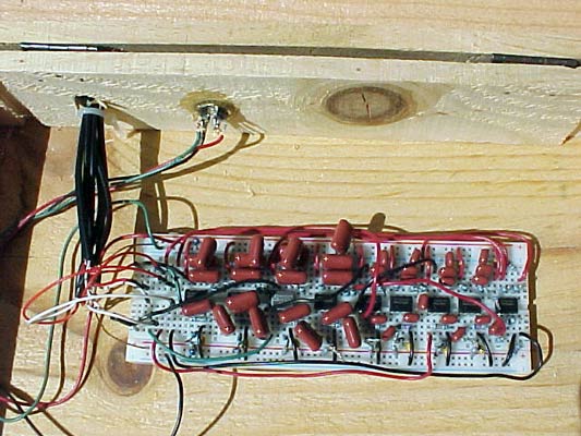
Here you see the box opened up. The boxis really too big; the board has room to do laps if it wanted - but this was thebox I had handy. I drilled 2 holes for I/O. One is for the power input. The other is for the RCA ins and outs. I used RCA cables cut in half. To these, I soldered small pieces of solid wire (cut resistor tails) to makeit easier to plug into the board. I used heat-shrink on these connections todiscourage cross-shorting between them. I tied all RCA GNDs to one piece ofsolid copper wire, which I plugged into my board (tough to see). The whitewires are the left channels (in, out high, out mid, and out low). The red wiresare for the right channles. Note that because all the GNDs are tied together,I only have 1 connection to the board for each channel.