Kit Supply
This link is for those people who intend to build their own power supply from my DIY PS kit. If you are buying a kit from me internationally, first thing to consider is what voltage regulators you have, and what type of transformer you need to get. If you live in the US, and bought a PS kit from me, then I probably sent you the correct trans for you application. If you are not buying a kit from me, you can use this page to help build your own supply using local parts.
Power Supply Discussion
I've read the data books, and looked at many designs in texts and on the web. I have since built several power supplies, all of which work well. They are really not that complex. I've seen power supplies virtually identical to the one in this kit used in high-end professional active crossovers. I've had some questions about the supply, so I'm providing this short tutorial:
Transformer: Steps AC down to lower voltage. There are 2 basic types of transformers you can use to build a DIY dual voltage (+/-15VDC) power supply for op amps:
30VAC center-tapped (CT) transformer: This type of trans is the most commonly seen type in text book designs for building a dual-output DC power supply. There are 3 wires at the output: 15V-0-15V. The 15V sections are out of phase with each other. An equivalent type of trans is the 15VAC dual output trans. This type has 4 wires at the output. If you connect the 2 center wires (one wire from each of the 15V sections), it will behave the same as the 30VCT transformer. Usually, this trans is purchased 'naked'. This means you have to connect a 120VAC (or 240VAC) wire to the trans from the wall socket. A chassis-mounted trans such as this has the disadvantage of bringing 110VAC into your chassis (hazzardous and noisy), but the advantage of a smoother signal feeding the big electrolytic caps (so you can make them smaller). Since this trans can be dangerous, I will not discuss it further on this page. If you want to use this type of trans, you are on your own, aside from the following info: The extact same schematic can be used, EXCEPT: you will disconnect the wire that goes from the center of the 2 big caps to the 15VAC input (column 23 in the layout shown below). You will now apply 30VAC input to the same place where the 15VAC input was. Now connect the center tap of your 30VAC trans to GND (at the center of the 2 big filter caps).
15VAC single output trans: This type of trans (which I recommend for DIY power supply builders) only has 1 output consisting of 2 wires. This type of trans can be found as a "wall-wart" which drops down the large AC voltage to a smaller AC voltage right at the wall, and sends the lower AC voltage (15VAC or 12VAC) to the electronics box. This voltage is clearly safer to work with, but should still be treated with respect. Since it only brings 15VAC into your chassis, this trans has less potential to induce 60Hz (and harmonics) noise in your other circuits within your chassis. Therefore, shielding is much less of an issue. This trans can be made to work for a dual DC supply if you connect the rectifier bridge as a 'split voltage doubler'. This is what I did in the schematic and layout below. In this case, we can take the middle of this split as our circuit GND. Look at your voltage regulators I sent. If they say 78 and 7912, then you should look for a 12VAC trans, with about 200 mA or better for the subkit, and approx 400 mA for the full 3-way kit. If they say 78 and 7915, then look for a 14VAC to 17VAC trans at 250 mA or better for the subkit, and 500 mA or better for the full 3-way.
Rectifier: Diodes turn the AC into a pulsing DC. Pulse peak = 1.4 X trans output voltage rating. A voltage doubling rectifier gives 2 of these. One is +, and the other is - relative to the reference point.
Input Filtering Caps: Big electrolytic caps to smooth the pulsing DC sent to the voltage regulator. I usually give 1000 uF, 63V German radials (center pin = +). Degree of smoothing depends on circuit load (power consumption) and the size of the big caps. The bigger the load, the bigger the req'd filter caps. Pulsing DC should not sag below 3 volts above the regulated voltage. A small ceramic cap in parallel may help remove high freq noise near the regulator's terminals. For referance, one version of my 3-way kit took about 70 mA from each rail.
Voltage Regulators: The 78XX / 79XX are the standard modern positive and neg voltage regulators. The number in place of the XX tells what the output voltage is. These regulators need no dressing besides in and out filtering caps. These are the regulators I've seen in professional equipment. The LM317 / 337 is a slightly newer regulator. It requires a few resistors to set the voltage. For peak performance (line regulation), it needs an additional electrolytic cap to ground. Some say that the LM317 / 337 may be slightly better in certain applications (see below). One advantage of the 317 / 337 is that the output voltage can be programmed by an external resistor. This make it easier to mate them to any arbitrary trans you have laying around.
I found the easiest layout used the 78XX/79XX regulators. This is what the kit PS shown in the pictures below is based on. I may have provided some of you with the 317/337 regulators at special request. I recently made a layout for these regulators, but it is not available online at this time.
Protection Diodes: You may place diodes around the regulators to give the currents a path around the regulators in case you hook something up wrong. These diodes also provide a path to drain the output filtering caps, if you use big ones (above 10uF). I included them in the schematic and photos below. You are provided them, but don't NEED them, unless you increase your output filter caps.
Output Filtering: These caps buffer the output of the regulators. You don't need big ones because the regulators do the work. Some small caps (10uF or less) might improve the transient response of your PS output. Mixing different types of caps (poly/ceramic/electrolytic/tantalum) in series at the PS output may offer advantages over having just 1 type. The "faster" of these output caps could be placed on the filter board itself if you like. The main XO kit typically includes a pair of mono ceramic caps to bypass the supply rails next to each dual op amp. These are recommended, but you can use them on every-other (alternating) dual op amp instead of every single one if you want.
Modern op amps have a power supply rejection ratio of about 100 dB. This means that you probably don't even need your supply to be regulated. I've talked to a few people who built some filters without regulation at all (just big filter caps), and they could still hear no noise. Therefore, I wouldn't spend tons of time worrying about the exact nature of your regulation. Note that in certain OTHER audio applications, regulation is more important. If you need very high gain (such as in a mic preamp), regulation is more important. My L-R crossover realizes no gain (gain of 1). In any case, modern regulators are cheap, and op-amp power supply designs are simple. An excellent, regulated supply can be built with this kit, regardless of which regulators you choose.
Here are the photos:
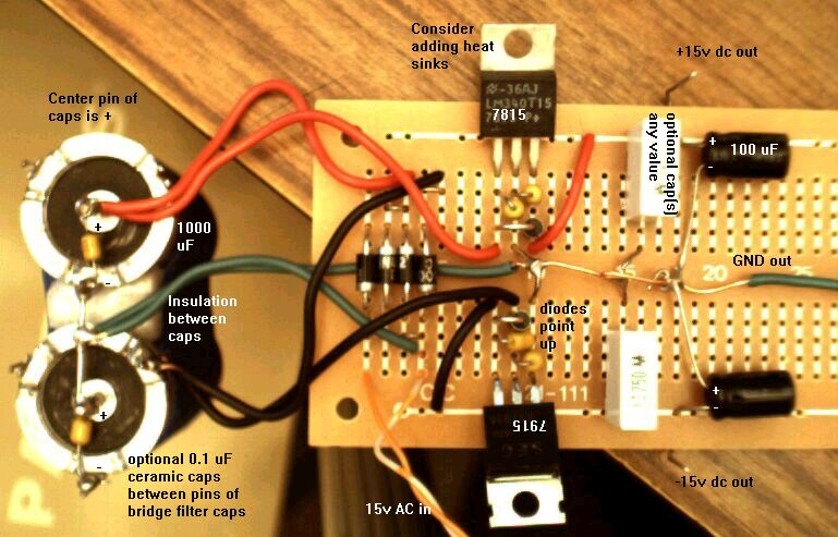
1) Here's a photo of one version of the PS. Note that the electrolytic caps have polarity (+ and -), and must be connected correctly. Compare the photo to the layout and schematic below. Note how the big metal caps are not allowed to touch each other electrically! Note the 2 wires twisted together at the bottom left. These are carrying 15VAC from an AC wall-wart transformer. This photo should help you as you build.
2) Here is the layout. Note that the board numbering is different, but the relative layout is the same. Compare diodes in schematic form to the photos of the diodes above to understand the correct polarilty (the arrow points to the silver stripe). The protection diodes in column 33 in the figure below were not included in the above photo. The above photo also shows optional cap(s) on the output.
3) Here's the schematic for your interest. Several optional caps are not shown.
Here are some links to DIY op-amp power supplies:
App Note: Improving Power Supply Reliability with IC Power Regulators: http://www.national.com/an/AN/AN-182.pdf
Supplies using 78XX / 79XX regulators:
See Erik Brewster's at: http://home.inreach.com/ebrewste/cross.html (near the bottom of the page). This is about as simple as it gets. You can use 1000 uF on the input, and up to 10uF and the output.
Luc Henderieckx's page: Power Supply and Balanced Input jpg. This one uses input 'snubbers.' Make sure those input R's are rated at at least a few watts.
National's Datasheet on the 7815: http://www.national.com/pf/LM/LM7815C.html
Supplies using LM 317 / 337 regulators:
Matt Tucker's http://kahuna.sdsu.edu/~tucker/diyaudio/xover.html (near the bottom of the page). This is about as simple as it gets. You can use 1000 uF on the input if you like. You can use up to 10uF and the output without adding protection diodes.
National's Datasheet: http://www.national.com/ads-cgi/viewer.pl/ds/LM/LM117.pdf
Supplies using other types of regulators:
Please see Greg Robert's advanced power supply (a 'seasoned tweeker' who uses my kit) at: http://communities.msn.com/DIYElectronics